⏱️ 9-10 min read
A walkthrough of the graphics pipeline and the unique way mobile GPUs render scenes.Topic too clichéd? Maybe. Idea was to write a refresher for myself so that I can come back to it (atleast somebody should use it ;) ). But if you’ve spent any time in the GPU world — as a graphics programmer, hardware architect, performance engineer , yada , yada , yada — you’ll know the feeling: sooner or later, you always return to the basics of the pipeline. There’s something magical about how a humble vertex transforms into the breathtaking pixels lighting up your screen. Even after years of working on GPUs, that journey still feels like sorcery.
What began for me as simply memorising pipeline stages has become the foundation for every debug session, every bottleneck hunt, every architectural choice, and every rendering optimisation. And as I grew in my career, one question kept nagging me: if all mobile GPUs follow the same pipeline, why does one architecture outperform another?
So… drumroll please… this article won’t tell you which GPU is “better” — sorry for the clickbait 😅. Instead, I’ll walk you through the basic framework of the mobile GPU pipeline, and along the way, we’ll see how two giants — ARM Mali and Qualcomm Adreno — approach the same problems through very different lenses.
If you’re still with me (thank you), let’s dive into the good stuff.
1. How a GPU Understands Your Scene: The Core Inputs
The output of any great image depends on how thoughtfully the scene is constructed. A scene is made up of backgrounds, objects, lights, materials, and surface details. Each of these needs information at different levels of detail — geometry, colour, textures, illumination, normal maps, and many other attributes.
But don’t get overwhelmed at the start.
To create even a single image using a GPU, we first need to define the objects in the scene. At the most fundamental level, this comes down to three key ingredients:
a. Define where things are — Vertex Buffers
These store the positions of points (vertices) in 3D space. Together they form the skeleton or structure of
every object in the scene.
b. Define how things look — Textures
Textures provide colours, patterns, roughness, normals, and other material properties that make objects appear
believable without increasing geometric complexity.
c. Define how things are drawn efficiently — Index Buffers
Instead of duplicating vertices, index buffers let the GPU reuse shared vertices to form triangles. This saves
memory and boosts rendering performance.
Core Data Structures at a Glance
| Component | Definition | Example | Benefits | Contents |
|---|---|---|---|---|
| Vertex Buffer | Stores vertex data (points in 3D). Provides the raw geometry that defines shapes. | Cube corners | Enables geometry that can be culled, clipped, and transformed with minimal CPU→GPU transfers. | Position, Colour, Normals, UV coordinates |
| Index Buffer | A list of integer references (indices) pointing into the vertex buffer to reuse vertices when forming triangles. | Square with shared corners | Reduces duplication, improves cache locality, and lowers memory usage. | List of integers |
| Textures | Images (2D, 3D, or procedural) mapped onto geometry. Add realism and detail without increasing geometry complexity. | Brick wall texture | Optimise rendering via compression, filtering, and mipmapping. | Diffuse/Albedo, Normal, Roughness, Displacement maps |
Once these are in place, the GPU has enough information to start its favourite job: turning triangles into pixels.
2. A Quick Tour of the Graphics Pipeline (GL / DX / Vulkan)
The GPU pipeline is the sequence of steps that transforms 3D data (vertices, buffers, textures) into the final 2D image displayed on your screen.
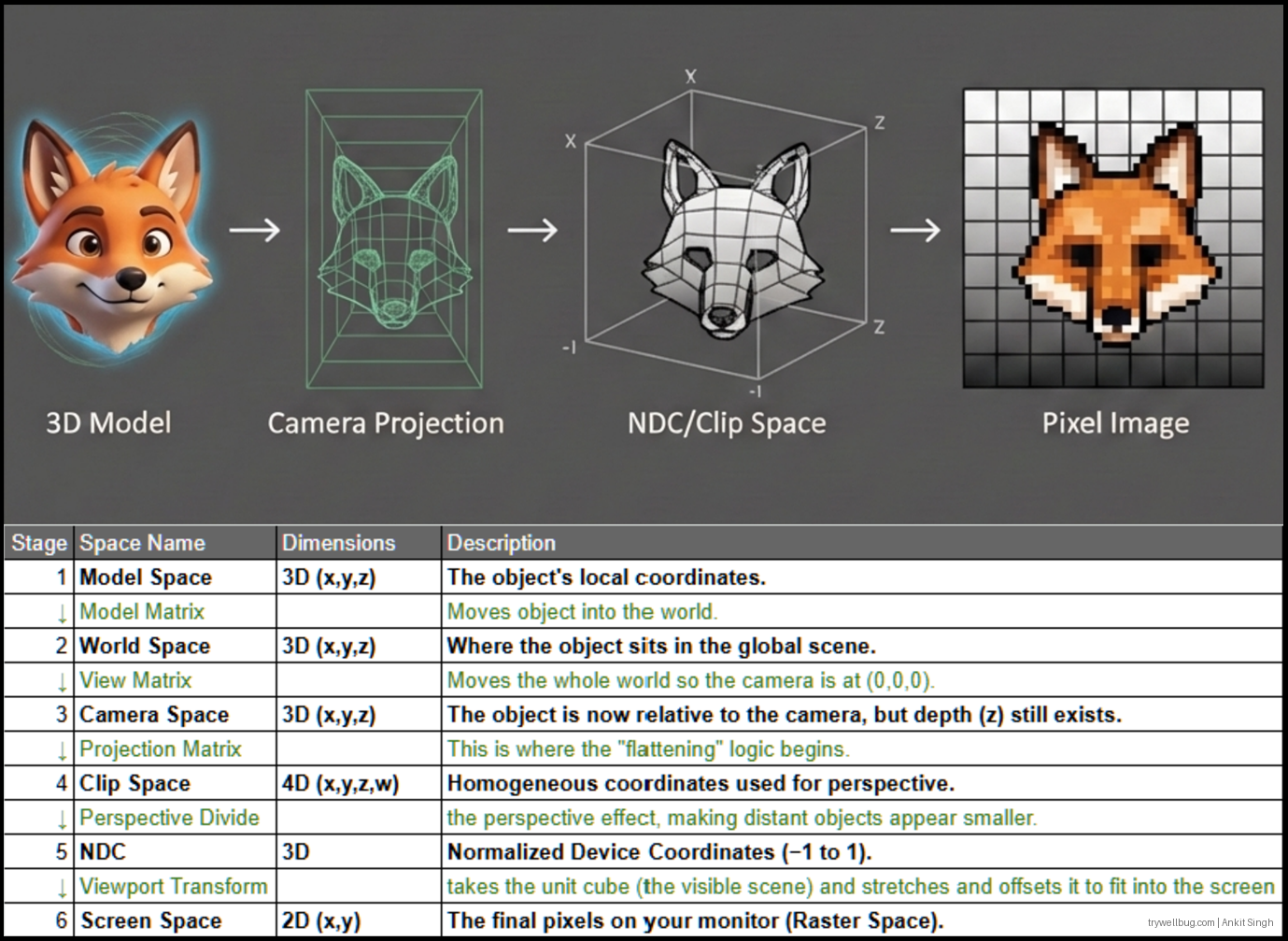
If you’re new to this whole “3D becoming 2D” idea, do yourself a favour —
don’t scratch your head, scratch a pixel.
(Yes, I am absolutely pointing you to the legendary learning site Scratchapixel.com.)
The pipeline isn’t just a straight, simple conveyor belt. Each stage is deeply optimised, massively parallel, and often powered by specialised fixed-function hardware designed to do one thing insanely fast.
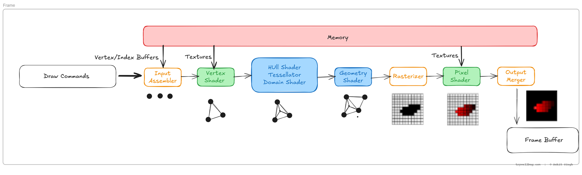
In the diagram:
- 🟡 Yellow boxes represent fixed-function hardware.
These stages perform highly specialised tasks (like vertex assembly, rasterisation, depth/stencil tests) at incredible speed. Their behaviour is standardised and used in almost every frame, so they’re not programmable. - 🟩 Green boxes represent programmable shaders used frequently.
These are the workhorses — the Vertex Shader and Fragment/Pixel Shader. They run user-written code millions or billions of times per frame, controlling transformations, lighting, and materials. - 🟦 Blue boxes represent programmable shaders used less often.
Tessellation and Geometry Shaders live here. They offer powerful capabilities (dynamic subdivision, procedural geometry), but many engines skip them on mobile due to performance costs or lack of native hardware support.
Input Assembler
Gathers vertex and index buffers and forms primitives like triangles.
Fun detail:
This stage does zero math. It simply streams data from memory using dedicated fetch hardware,
respecting cache lines and vertex reuse. Efficient layouts (AoS vs SoA, interleaved attributes, alignment) can
noticeably affect bandwidth and cache behaviour.
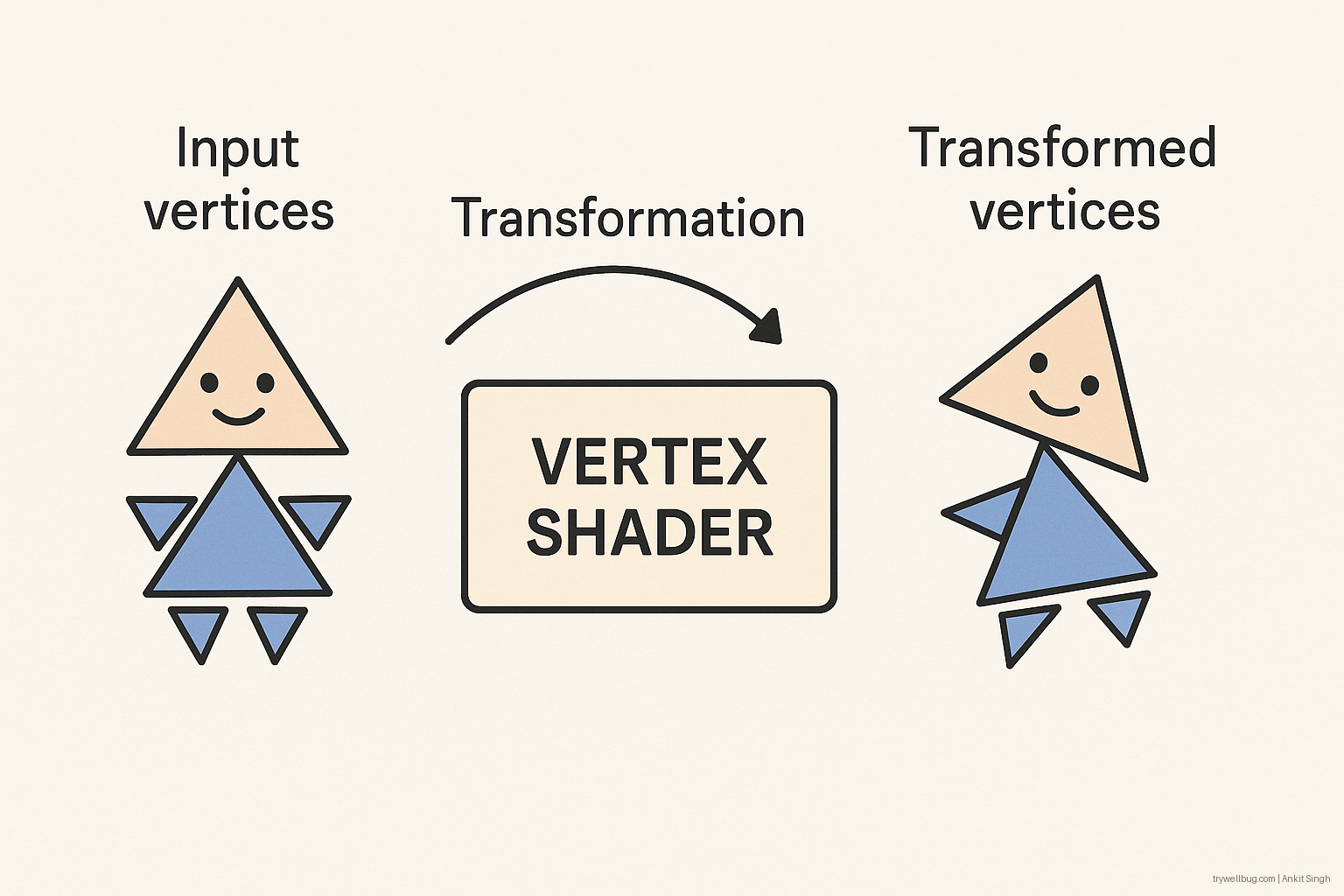
Vertex Shader
Transforms vertices ( scale/rotation/..) into clip space and applies per-vertex operations.
Fun detail:
Vertex shaders run in SIMD lanes with typically low divergence. Modern GPUs aggressively batch vertices and
cull invisible geometry early to avoid wasted work downstream.
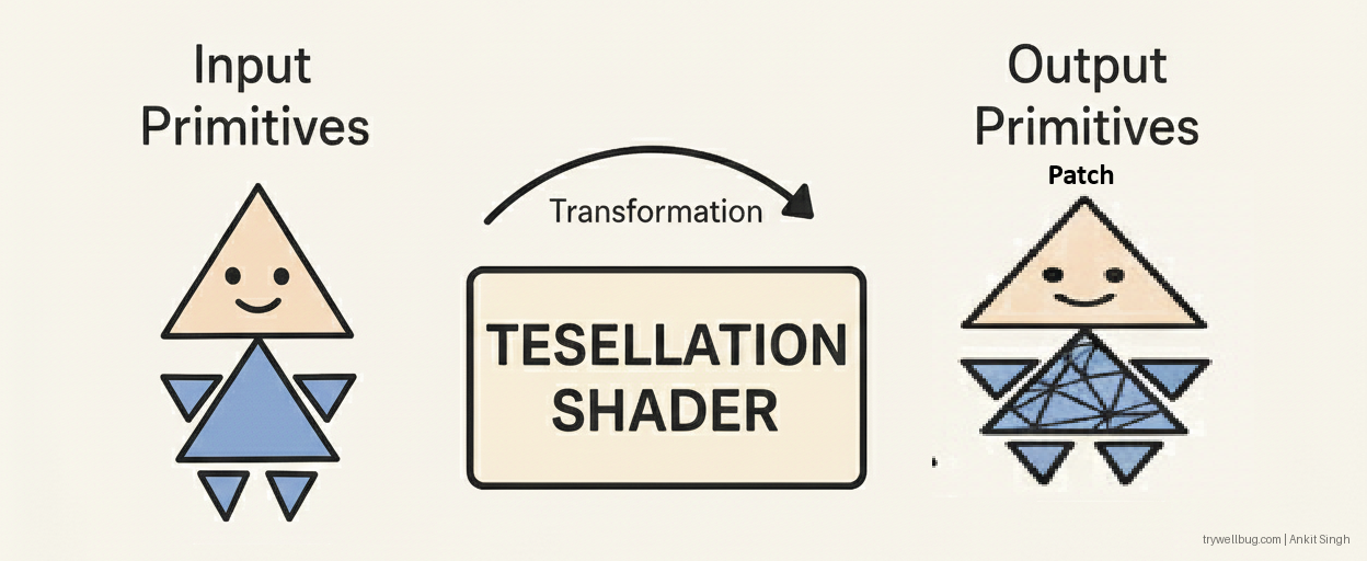
Tessellation (Hull Shader → Tessellator → Domain Shader)
Refines or subdivides geometry surfaces on the fly (based on patch data). It consists of two programmable stages (Hull, Domain) and one fixed-function stage (the Tessellator).
Fun detail:
Tessellation is powerful on desktop/console (for displacement mapping, smooth characters, terrain) but is
usually missing in hardware on mobile. When it exists, it’s often not widely used by popular mobile games.
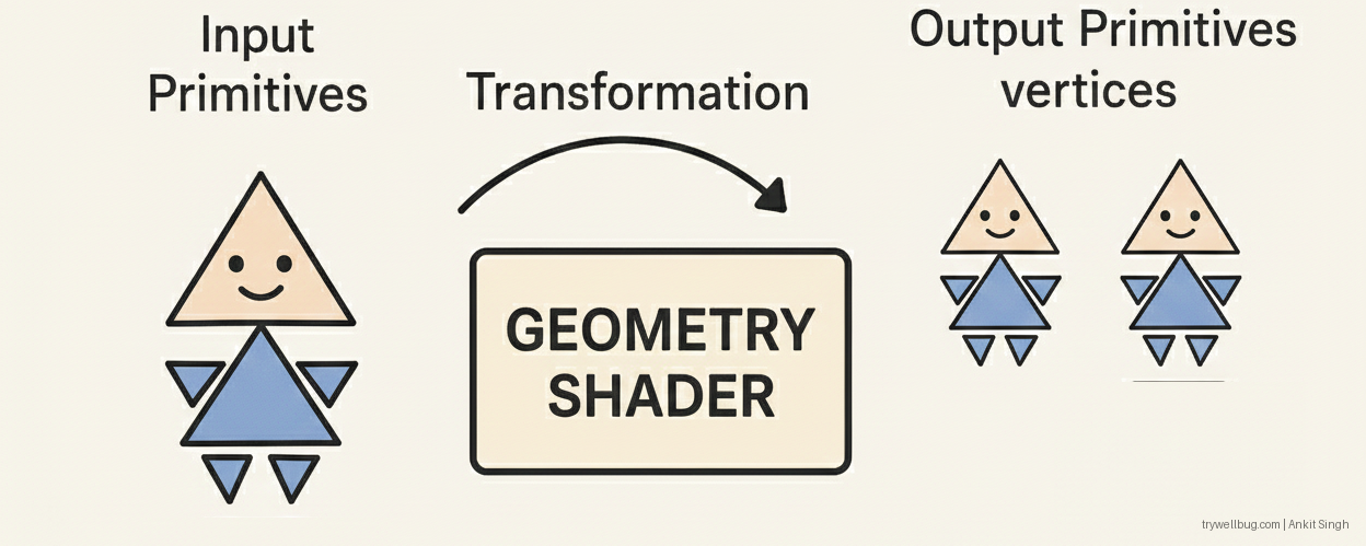
Geometry Shader
Runs per primitive and can:
- Expand points into quads or billboards
- Create shadow volumes
- Generate procedural or debug geometry
- Do layered rendering to cube maps or texture arrays
Fun detail:
Despite its flexibility, the Geometry Shader is generally slow because it breaks the GPU’s optimal batching
model and increases memory traffic. Many modern engines avoid it or replace it with compute-based mesh
generation or Mesh Shaders (DX12/Vulkan).
Rasterizer
Converts triangles into pixel-sized fragments.Geometry finally stops being math and starts becoming pixels.
Fun detail:
The rasterizer uses edge equations and barycentric interpolation in fixed-function hardware. It can perform
early depth testing and kill large blocks of fragments before they reach the pixel shader — saving huge
amounts of work.
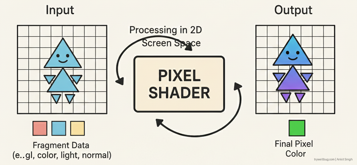
Pixel (Fragment) Shader
Runs per fragment, doing shading, texture sampling, lighting, BRDF evaluation, etc.
Fun detail:
This is the most expensive stage on most GPUs. Heavy texture access, complex material graphs,
divergent branches, and overdraw can tank performance. Fragments are usually processed in 2×2
quads so derivatives (for mipmaps, etc.) can be computed cheaply.
Output Merger
Performs depth/stencil tests, blending, MSAA resolves, and writes final colour values to the render target.
Fun detail:
Blending is still fixed-function and highly optimised for contiguous memory writes. Modern hardware can combine
multiple fragment results before hitting memory, but unordered or random writes can still thrash the ROPs
(Raster Operations Pipeline).
The final pixel values are written to the framebuffer — and a few milliseconds later, the display scans them out to your screen.
OpenGL vs DirectX Names (Cheat Sheet)
# OpenGL vs DirectX Pipeline Stage Names

| Pipeline Stage                  | OpenGL Name                                           | DirectX (DX11/DX12) Name          |
| --------------------------------| ------------------------------------------------------ | --------------------------------- |
| Vertex Input                    | Vertex Specification (VAO / VBO / glVertexAttribPointer) | Input Assembler (IA)           |
| Vertex Shader                   | Vertex Shader (GLSL VS)                               | Vertex Shader (VS)                |
| Tessellation Control            | Tessellation Control Shader (TCS)                     | Hull Shader (HS)                  |
| Tessellator (Fixed Function)    | Tessellator                                           | Tessellator                       |
| Tessellation Evaluation         | Tessellation Evaluation Shader (TES)                  | Domain Shader (DS)                |
| Geometry Shader                 | Geometry Shader (GS)                                  | Geometry Shader (GS)              |
| Clipping & Projection           | Clipping + Perspective Divide (Fixed)                 | Clipping + Viewport Transform     |
| Rasterisation                   | Rasterizer                                            | Rasterizer Stage                  |
| Fragment / Pixel Shader         | Fragment Shader (FS)                                  | Pixel Shader (PS)                 |
| Depth / Stencil / Blend         | Per-Fragment Operations                               | Output Merger (OM)                |
| Render Output                   | Framebuffer                                           | Render Targets (RTV/DSV)          |
3. Rendering in Mobile GPUs
Before comparing how mobile GPU hardware works, we need to reveal the not-so-secret sauce behind almost every modern mobile GPU:
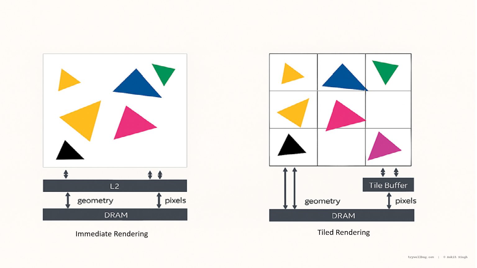
They almost never use classic Immediate Mode Rendering (IMR) — the pipeline mental model many of us learnt from desktop GPUs.
Instead, mobile GPUs lean heavily on Tile-Based Rendering (TBR).
Why? Because the hardware budgets are radically different.
- Desktop GPUs
Memory: GDDR6 / GDDR6X / GDDR7
Bandwidth: 500–1500 GB/s+
Power: 300–400 W GPU budget - Mobile GPUs
Memory: LPDDR4 / LPDDR5
Bandwidth: ~30–60 GB/s
Power: 2–5 W for the entire SoC GPU
With that kind of bandwidth and power gap, taking a naïve desktop-style IMR pipeline and dropping it into a phone would be catastrophic.
In a traditional IMR pipeline, every triangle and fragment typically involves:
- Multiple framebuffer reads/writes
- Depth operations going to/from DRAM
- Blending operations going to/from DRAM
On a 400 W desktop card, this is manageable.
On a 3 W mobile GPU, it kills performance and thermals.
Why Tile-Based Rendering Wins on Mobile
Tile-Based Rendering reorganises the pipeline around locality and on-chip memory:
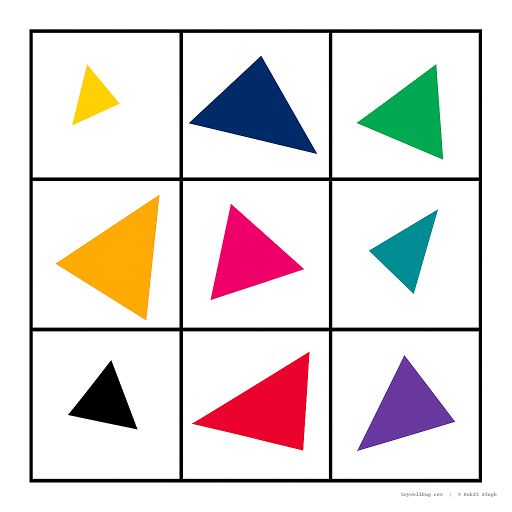
- The screen is divided into tiles/bins, and triangles touching each tile are collected.
- Each tile is processed entirely inside an on-chip tile buffer (SRAM).
- Only the final resolved tile is written out to DRAM.
Fewer DRAM accesses → less bandwidth → less heat → more sustained FPS.
This strategy makes sense for mobile because it:
- Can cut bandwidth by 50% or more
- Dramatically reduces power consumption
- Makes MSAA much cheaper, since samples stay on-chip
- Fits within the strict 2–5 W power envelope
Variants of Tile-Based Rendering
Different vendors implement tiling differently:
- Fully Tiled
ARM Mali (Bifrost, Valhall), Apple GPUs, PowerVR
Almost everything goes through the tiler and on-chip buffers. - Hybrid Tiling (TBDR: Tile-Based Deferred Rendering)
Qualcomm Adreno
Uses tile binning + partial immediate-mode behaviour where needed.
And yes, it sounds suspiciously like TL;DR — which better not happen to this article 😄.
Why Tiling Changes Everything
This is why I’m stressing Tile-Based Rendering before jumping into the detailed pipeline. It’s not just a nice optimisation; it fundamentally reshapes mobile GPU architecture.
Because we must save bandwidth and keep as much work on-chip as possible, the GPU needs to avoid processing geometry or fragments that won’t contribute to the final image. This leads to a two-pass strategy:
1. Binning Pass
The screen is divided into small tiles. The GPU determines which triangles touch which tile, performing a coarse visibility classification. Only the geometry relevant to each tile is queued for further processing.
2. Rendering Pass
For each tile, only the actually visible triangles enter rasterisation. Depth tests, blending, MSAA, and colour writes all happen inside the on-chip tile buffer. Only the final resolved tile is written to DRAM.
This architectural strategy drives a whole ecosystem of hardware choices:
- Dedicated visibility hardware for binning
- Concurrent binning and rendering passes
- Complex resource balancing between tiler, shader cores, texture units, and memory controllers
- Efficient tile stitching to compose the final framebuffer
- Dynamic choices for tile size and tile memory usage
- Special on-chip structures: tile caches, hidden surface removal buffers, local storage/shared memory
These aren’t minor tweaks — they make mobile GPUs a different species compared to traditional desktop GPUs.
Tile-Based Rendering is therefore not just an optimisation;
it’s the reason mobile GPUs can exist within a 2–5 W thermal envelope while still pushing
console-like visuals.
Conclusion
So… this feels like a good place to end my first blog everrrrrrrrrrrr :) ( Sorry got excited ... Ctrl Ctrl Uday ) .
Now you understand why I spent so much time talking about Tile-Based Rendering before even touching “How does the triangle actually move inside ARM vs Qualcomm?”.
If you don’t first appreciate why mobile GPUs are built the way they are, then explaining how triangles move through them makes no sense. The hardware is different because the constraints are different — and that single fact shapes everything else.
Yes, I did slightly clickbait you with the promise of ARM vs Qualcomm pipelines (guilty).
But don’t worry — I haven’t forgotten the real question you came here for:
“How does a triangle actually travel inside a mobile GPU?”
That is coming next.
And just like my favourite Bollywood saga — Gangs of Wasseypur Part 2 — I’m saving the real carnage, drama, and architectural twists for Part 2.
In the next chapter, I’ll break down how two giants of mobile graphics —
Qualcomm Adreno and ARM Mali —
take completely different approaches to the same fundamental question.
Can it be a blockbuster of a deep dive into their architectures?
We’ll see. 😉
Keep TRYing, stay WELL, and keep deBUGing.